

Task 7 - Soldering a simple circuit along with making the circuit design on EAGLE (Individual Task)
- EmadMaximos
- Oct 14, 2018
- 12 min read

Updated: Oct 22, 2018

Task Objective
The main objective of this task was to learn about and practice one of the widely known and most essential techniques that is used in electronics to make permanent circuits which is "Soldering", this is in contrast to making prototype or test circuits using mainly breadboards. The task was to solder a simple circuit consisting of a push button, a resistor, and a LED onto a prototype board with copper pads using the necessary soldering tools and equipment.
Introduction to Soldering
Overview
Soldering is a process in which two or more metal items are joined together by melting and then flowing a filler metal into the joint—the filler metal having a relatively low melting point. It is used to form a permanent connection between electronic components. The metal to be soldered is heated with a soldering iron and then solder is melted into the connection. Only the solder melts, not the parts that are being soldered. As mentioned above, you can alternatively use a solderless breadboard to make test circuits, however if you want your circuit to last for more than a few days, you will want to solder the components together.
Materials and Equipment
Below is an illustrative figure showing the different equipment and materials that are used to aid in soldering to achieve a successful soldered circuit.

So, let's go through and discuss each of the elements presented in the figure above along with their individual functions:
Soldering Iron: is used to heat the connections to be soldered. For electronic circuits, you should use a 25- to 40-watt (W) soldering iron. Higher wattage soldering irons are not necessarily hotter; they are just able to heat larger components. A 40-W soldering iron makes joints faster than a 25-W soldering iron does. Soldering irons can be purchased at hardware stores and at most large department stores.
Rosin core solder: has a lower melting point than the metals that are being connected do. The solder melts when it is heated by the soldering iron, but the metals being joined will not melt. The rosin core acts as a flux. It prevents oxidation of the metals that are being connected, and enhances the ability of the solder to "wet" the surfaces that are being joined. For most electronics work, a solder with a diameter of 0.75 to 1.0 mm is best. Thicker solder might make soldering small joints difficult and also increases the chances of creating solder bridges between copper pads that are not meant to be connected. An alloy of 60/40 (60% tin, 40% lead) is used for most electronics work, but lead-free solders are available as well.
Stand for holding the soldering iron: it is important to always keep the hot iron in its stand when not in use. There are a variety of stands available.
Sponge: The damp sponge is used to clean the tip of the iron.
Prototype board: is used to assemble the circuit. Prototype boards have copper tracks or pads for connecting components.
Solder braid: this is used to remove solder. To use the braid, place it over the solder to be removed and heat it from above with the iron. The solder will flow into the braid. Solder braid is used to extract an electronic component that is soldered onto a board. It is also used to reduce the amount of solder on a connection.
Wire strippers: can be adjusted to strip the plastic covering off of various thicknesses of wire.
Steel wool or fine sandpaper: used to clean connections prior to soldering as solder will not flow over a dirty connection. (not shown in above figure)
Preparations for soldering
These are some guide steps to follow in order to carefully prepare yourself for the soldering process:
1. Place the soldering iron in its stand and plug it in.
2. Wait for the soldering iron to heat up.
3. Moisten the sponge.
4. Wipe the tip of the iron on the damp sponge in order to clean it.
5. Melt a little solder on the tip of the iron.
This is called tinning and it will help the heat flow from the iron's tip to the joint.
The solder should flow onto the tip, producing a bright shiny surface.
If the solder does not flow onto the tip, clean it by wiping it on the wet sponge.
When tinned, wipe excess solder off on the wet sponge.
You do not need to tin the tip before every joint, but you should re-tin it if it has gone dull when the soldering iron has not been used for a few minutes.
Check the manufacturer's instructions related to tinning the tip.
6. The tip of the soldering iron should be a shiny silver color. If it is black and pitted, replace it with a new one.
Soldering Process
The soldering process can be described in the following sequential steps that one needs to perform to ensure having a correctly soldered circuit:
1. First of all, solder needs a clean surface on which to adhere, therefore you should:
Buff the copper foil of a PC board with steel wool before soldering.
Remove any oil, paint, wax, etc. with a solvent, steel wool, or fine sandpaper.
2. To solder, heat the connection with the tip of the soldering iron for a few seconds, then apply the solder as shown in the figure below.
Heat the connection, not the solder.
Hold the soldering iron like a pen, near the base of the handle.
Both the tip of the iron and the solder wire should be at an angle of about 45 degrees with copper pad on the board.
Both parts that are being soldered have to be hot to form a good connection.

3. Keep the soldering tip on the connection as the solder is applied.
Solder will flow into and around well-heated connections.
Use just enough solder to form a strong connection (try not to use an excessive amount of solder in each joint as much as possible).
4. Remove the tip from the connection as soon as the solder has flowed where you want it to be. You should remove the solder, then the iron.
5. Don't move the connection while the solder is cooling.
6. Don't overheat the connection, as this might damage the electrical component you are soldering.
Transistors and some other components can be damaged by heat when soldering. A crocodile clip can be used as a heat sink to protect these components as shown in the following figure.

7. Soldering a connection should take just a few seconds.
If it is taking longer, you need to troubleshoot the problem.
8. Inspect the joint closely. It should look shiny.
If you are soldering a wire (called the lead) onto a PC board (on the track), it should have a volcano shape as shown in the figure below.
If the connection looks bad, reheat it and try again.

9. Wipe the tip of the iron on a damp sponge to clean it. The tip should now be shiny.
10. Unplug the soldering iron when it is not in use.
Safety, Tips and Troubleshooting
Safety Precautions
1. Caution: A soldering iron can heat to around 400°C, which can burn you or start a fire, so use it carefully.
2. Unplug the iron when it is not in use.
3. Keep the power cord away from spots where it can be tripped over.
4. Take great care to avoid touching the tip of the soldering iron on a power line. If a power cord is touched by a hot iron, there is a serious risk of burns and electric shock.
5. Always return the soldering iron to its stand when it is not in use.
6. Never put the soldering iron down on your work bench, even for a moment!
7. Work in a well-ventilated area.
Tips
Reliable operation of a circuit with soldered connections depends on good soldering practices. Here are some tips for successful soldering:
1. Plan before you start to solder. Identify all the parts that you will be using.
2. It is helpful to attach each part to a piece of paper and write what it is and its value (for example, resistor #1: 100 ohms).
3. Some components, such as LED's, must be placed the correct way around in order to function.
4. The following is a suggested order for the installation of various components:
Integrated circuit (IC) holders (note the orientation). The IC will be added later.
Resistors.
Capacitors, less than 1 micro farad.
Large capacitors, 1 micro farad or greater, note the orientation.
Diodes, note the orientation.
LED's, note the orientation.
Transistors, note the orientation.
Solid wire connections between components on the board. Solid wire is fairly rigid, so it will stay in place once attached.
Stranded wire to parts that are connected by wire to the circuit as it is more flexible than solid wire.
Integrated circuits.
Common Problems and Troubleshooting
1- Solder will not flow.
The parts to be joined may be dirty. Remove the solder and clean the parts.
2- The connection looks grainy or crystalline.
Parts were moved before the solder was allowed to cool.
Reheat to form a good joint. You may need a larger soldering iron to heat connections adequately.
3- The tip is oxidized.
Clean the tip with a damp synthetic sponge while the iron is hot.
To avoid oxidizing the tip, do not leave the iron plugged in when not in use.
Do not use the iron at a higher temperature than is necessary to melt solder.
4- There is too much or too little solder.
Using too much solder can cause a solder bridge, which means that two adjacent joints are accidentally connected.
Using too little solder might result in poor electrical continuity between the board and component. The connection should be smooth, shiny, and rigid.
And here is a short video that teaches soldering for beginners and gives some important guides and tips:
Steps of soldering my circuit
Now that we have gone through the detailed introduction of soldering, I will show and discuss all the steps that I went through to accomplish this soldering task. The task was divided into two main steps: (a) Making the circuit design and PCB on EAGLE and (b) Soldering the circuit.
First, I drew a free-hand sketch of my circuit to showcase all the components used along with the connections as shown in the figure below.

a) Making the circuit design and PCB on EAGLE:
This was my first time using the program called "EAGLE", so it was a nice experience getting to know all the program tools that I can use to make schematic circuit designs and printed circuit boards (PCBs). Moreover, the program is really simple and enjoyable to work with in addition to having an immense library that includes various electronic components. The steps of working on EAGLE were as follows:
1. Open "EAGLE Autodesk 9.1.3".

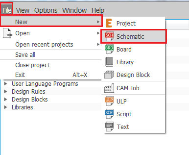
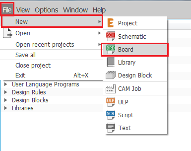
2. When the GUI of the program opens, you can choose either one of two things to do on EAGLE which are:
a) Schematic (To make a schematic design of your circuit).
b) Board (To make a Printed Circuit Board/ PCB out of your circuit).
By clicking "File", going to "New", and choosing either "Schematic" or "Board" as shown in the figures below.


3. I choose "Schematic" as I first start by drawing the schematic design of my circuit and the following GUI for schematic appears, as shown in the figure below, that we will be using.

4. Now, we go to "Options" and select "User interface" to change the background color. We can choose from either white, black, or colored background as shown in the figures below. I personally choose the white background as I'm used to it.


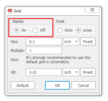
5. We can also make a grid in our background, if we so choose, as shown in the figures.


6. Then, we start assigning the commands for shortcuts so that we can work fast and easily on schematics. We go to "Options" also, but this time we select "Assign" and a window pops up and then we choose "New" to assign a new command. Our command list includes:
1) Ctrl+A, Command Name: Add, for adding a component from the library. 2) Ctrl+D, Command Name: del, for deleting a component. 3) Ctrl+J, Command Name: jun, for making a junction for each component. 4) Ctrl+M, Command Name: mov, for moving/ rotating a component. 5) Ctrl+W, Command Name: wire, for adding connection wires between components.
All the steps required for assigning our commands/ shortcuts are shown in the following figures below.


7. Now, we try the Console commands like typing " add ", as shown in the figure below, or alternatively pressing Ctrl+A to add a new component from the library.

8. The GUI window for "Add" appears, we start searching for our components by writing down their names or codes in the "Search" bar located at the bottom. We add each of our required components individually as shown in the figures below.
Important Notes:
This is the only way we can use to add a component in EAGLE. For example, if we are looking for a resistor and type in the word "resistor" in the console bar above the schematic the program won't understand! Therefore, we have to follow steps 7 and 8 to add a component.
When adding a component we should make sure that it has a PCB drawing, otherwise we won't be able to use it in making a PCB board for our circuit.
Sometimes a component can be found in the default Alphabetic library without needing to enter its name or code in the search bar.


9. By clicking "OK" after selecting the component that you want, this is how it looks like in the schematic, as shown in the figure below, and you can start clicking every where on the schematic to add more of the same component.

10. And this is after adding all the components.

11. Here I just adjust the orientation of some components by clicking on the component and pressing Ctrl+M to move it, in addition to right clicking on the component to make it rotate around.

12. Afterwards, we start adding junctions, which are the green dots shown below, by pressing Ctrl+J or writing "jun" in the console bar. We add them to all ends/ terminals of the components to ensure when using wires that the wire is correctly connected between the components.

13. Now, comes the time to use the wire command by pressing Ctrl+W or writing "wire" in the console bar. We add wires between components from one junction/ green dot to the other to have a final closed circuit as shown in the figures below.


14. By this point, the schematic circuit design is finished and now we go to making a PCB board out of this circuit by pressing the "Generate/ switch to board" icon in the toolbar at the top, then pressing "Yes" as shown in the figures below. This transfers us to the board GUI in EAGLE shown below.


15. So we start in the board GUI by assigning the commands for shortcuts so that we can work fast on the board. Again, we go to "Options", we select "Assign", and a window pops up and then we choose "New" to assign a new command. Our command list here includes:
1) Ctrl+M, Command Name: mov, for moving/ rotating a component. 2) Ctrl+P, Command Name: rip, for deleting wire connections on the board. 3) Ctrl+R, Command Name: rou, for routing new wire connections on the board.
All the steps required for assigning these commands/ shortcuts are shown in the following figures below.


16. We then select the whole circuit and move it to the GUI board work space, which is the black box in the middle, as shown in the figure below.

17. We need to set some design rules before working on our board like: the clearance space between wires and the minimum distance between the board and the outlines of our square work space. In order to do so, we go to "Edit", then select "Design rules" and a GUI window pops up. We set the following parts:
In the "Clearance" tab, we set the wire clearance to be 5 millimeters (mm).
In the "Distance" tab, we set the "Copper/ Dimension" to be 60 mil.
All the steps required for setting our design rules are shown in the following figures below.


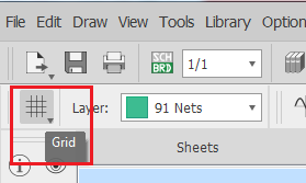
18. We also need to adjust our measuring units in the work space to be in millimeters (mm). Therefore, we go to the icon called "Grid" located at the top left corner of the window and press it. This opens up a small window GUI where we set the "Size" and "Alt" to be in mm as shown in the figures below.


19. Afterwards, we need to choose the PCB layer on which the wire connections will be made. We go to the tab named "Layer" also located at the top left corner of the window directly to the right of the "Grid" icon. Here, I choose the layer "16 Bottom" from the drop down list that appears, shown in the figure below, as we need to have our wires in the bottom layer, because the PCB that we will use will be having through holes and will not be a surface mount PCB.

20. We then slightly adjust the orientation of some components, as shown below, by clicking on the component and pressing Ctrl+M to move it, in addition to right clicking on the component to make it rotate around exactly like we did in the schematic to adjust our components.

21. Finally, we start routing our wire connections by pressing Ctrl+R. However, first we need to choose the wire style and width that we will use. I choose the wire style to be "Wire bend style 1" and a width/ thickness of 0.8128 mm, which is an appropriate width for our use, then we start the routing process as shown in the figures below.


22. And here we have our final PCB board circuit after routing all the wires.

Here is a screen recorded video that I made, however it was divided into three videos due to the recording time limitation of the application I was using. The videos show the whole process of making the schematic circuit design and the PCB board of my circuit on EAGLE:
b) Soldering the circuit:
In this step, I start soldering my circuit using the soldering equipment and materials like: the soldering iron and solder while following the preparations, steps, and tips of soldering that were discussed above in the introduction. The soldering iron is heated to a set temperature of 450 °C with the aid of the heater that comes with it so I had to be cautious while working. Here is the list of components I used to form my circuit:
1. Printed Circuit Board (PCB) with copper pads "Perforated Board".

2. Push Button.

3. 3V LED.

4. Resistor.

5. Short breadboard wires.

6. Arduino Uno as a Power Source supplying 5V.

Here are the front and back views of the final circuit after soldering.


Conclusion
In summary, soldering is a really essential and useful technique to learn in electronics that enables us to make permanent circuits for the use in a wide variety of applications including both prototyping and industrial ones. So, we encourage you to come visit us at FabLab in New Cairo (FLiNC) where you can learn and practice soldering, then start fabricating your own circuit! :D


Comments