

Task 11 - Computer Controlled Cutting (Laser Cutting)
- EmadMaximos
- Nov 12, 2018
- 3 min read

Updated: Nov 13, 2018

Introduction to Laser Cutting
Laser cutting is a precise method of cutting a design from a given material, in a two-dimensional (2D) space, using a CAD file to guide it. There are three main types of lasers used in the industry: CO2 lasers, Nd, and Nd-YAG. The most commonly used are CO2 machines. This involves firing a laser which cuts by melting, burning or vaporizing the material. You can achieve a really fine level of cutting detail on with a wide variety of materials. Bare in mind that CO 2 lasers can’t cut metals and hard materials, they can however engrave them.
Laser head and tolerance
The beam is emitted from what is called the "laser tube" and is reflected by several mirrors up into the "laser head" (like a periscope). Within the head is a lens that finely focuses the beam onto the material surface for cutting or engraving.
The kerf refers to how much of the material the laser takes away when cutting through (the width of the groove made while cutting). This varies from material to material and is also dependent on the laser beam tolerance i.e. the width of the beam. For the particular machine and material that we were using, ply wood 3 mm thickness, we found out the kerf range to be in between 0.15 - 0.3 mm.
Required Tasks
For the laser cutting assignment, it was required to do two main tasks:
Individual Task: Design, make, and document a parametric press-fit construction kit.
Group Task: Make test part(s) with varying cutting settings to test different aspects of the laser cutter machine like: Cut, Scan, Power, Speed, and kerf/ tolerance.
Individual Task
Task Objective
The main objective of this individual task was to make a parametric design press-fit construction kit using any CAD program of choice, use a program called "RDWorks" to prepare the .dxf extension files to be cut, then set up the laser cutter machine to cut the design files. The general idea behind this was to understand the concept and fundamentals of parametric design, get to work with and operate the laser cutter machine properly, and study the tolerance/ kerf of the machine to successfully achieve the target of making a press-fitting kit. The machine we used was "MORN MT3050D".
More about the laser cutter MORN MT3050D
MORN MT3050D is a portable laser engraving machine. It is suitable for small business or home business as it is easy for operation and transportation in addition to being much cheaper than other laser cutter machines.
The desktop laser engraver can also do both engraving and cutting on most of non metal materials such as: acrylic, wood, leather, plastic, fabric, cloth, rubber, paper, card board, MDF, PVC, ABS, glass, marble, stone etc.

What is a Parametric Design?
Parametric design is a process based on algorithmic thinking that enables the expression of parameters and rules that together define, encode and clarify the relationship between design intent and design response. The term parametric originates from mathematics (parametric equation) and refers to the use of certain parameters or variables that can be edited to manipulate or alter the end result of an equation or system.
Steps of making the task
This task was divided into three main steps: (a) Making the CAD designs, (b) Preparing the design files on "RDWorks V8", and (c) Cutting the designs on the laser cutter.
a) Making the CAD designs:
In this first step I decided to make three different designs, two on "OpenSCAD" and a more complicated one on "SOLIDWORKS" as I'm more used to it. First, I will go through the two designs that I made on OpenSCAD.
- Working with OpenSCAD:
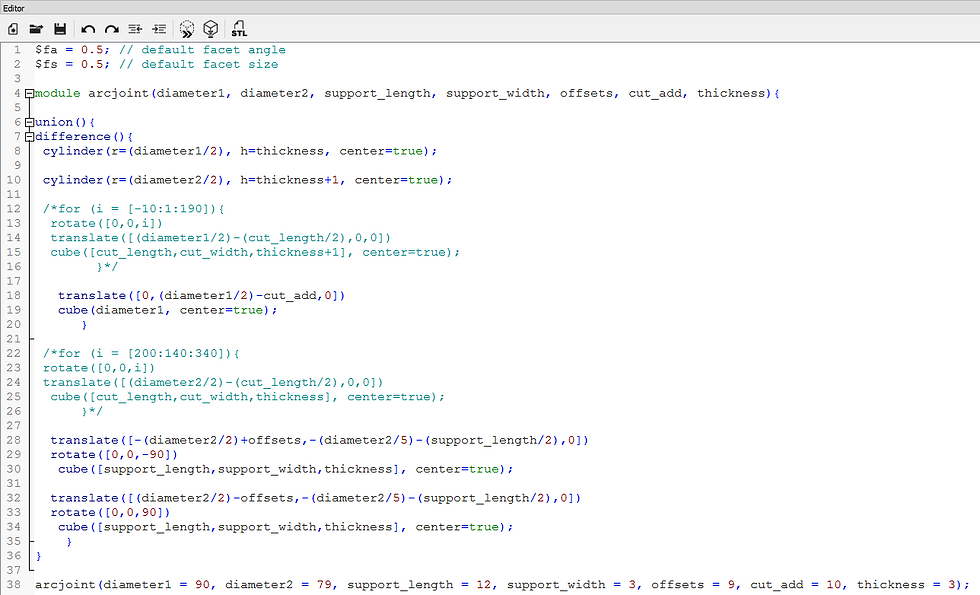
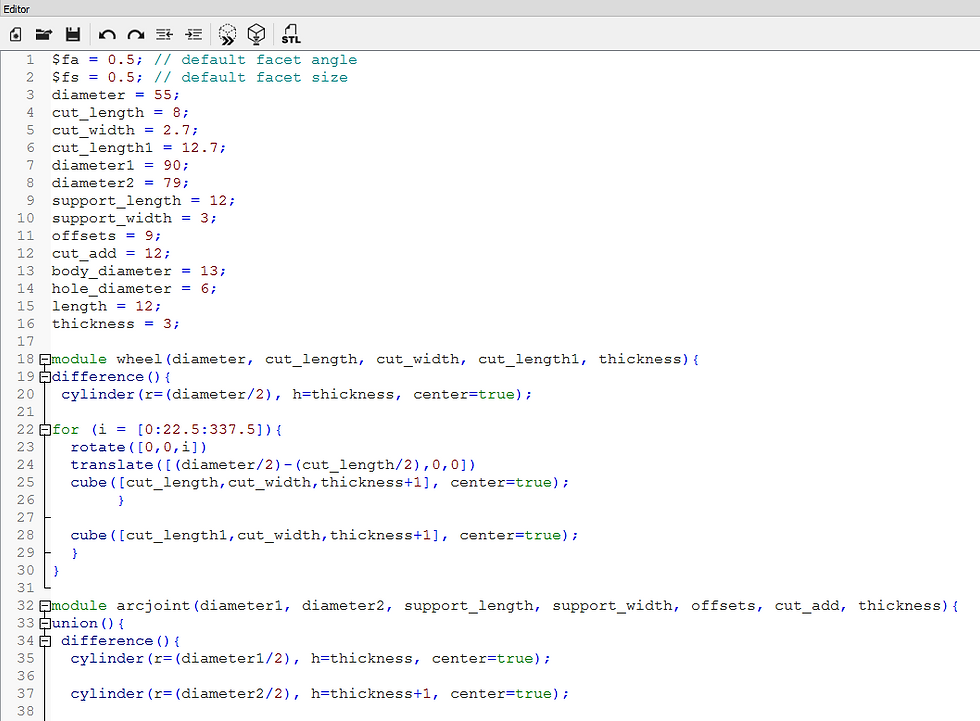
The special thing about using OpenSCAD to make a parametric design is that in this particular program you write lines of code to make a certain design, therefore in order to make a design parametric you simply write the code for the design in a module or function that takes all the design's parameters/ variables as inputs which you can then manipulate their numeric values to change or alter in the design as you might wish.
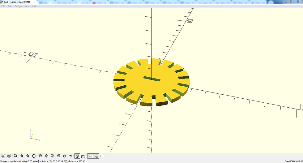
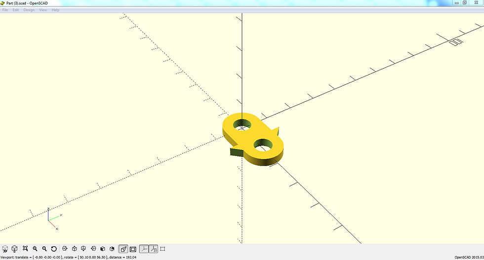
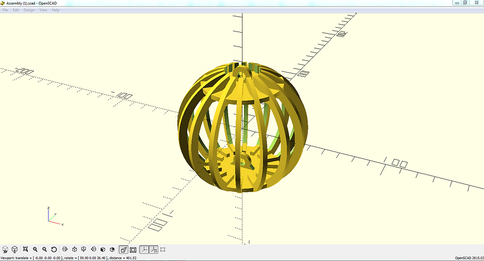
The first design I made was a construction kit for a "Cage Ball", the designs and codes for the individual parts of the kit along with its assembly are shown in the following figures.


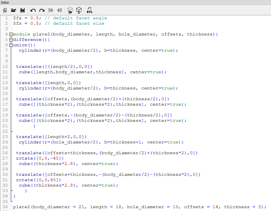
The second design I made was a "Spinner", the designs and codes for the individual parts of the spinner along with its assembly are shown in the following figures.


Comments