Task 4 - Making a CAD Design on SOLIDWORKS along with 3D Simulation and OpenSCAD Trials
- EmadMaximos
- Sep 28, 2018
- 8 min read
Updated: Oct 22, 2018
Task Objective
The main objective of the given task this time was personally interesting for me as we were asked to design anything or any model we want to be consisting of two parts, or more, and we had complete freedom in choosing the CAD program that we want to work with in addition to making a 3D simulation video for the designed model as a bonus part, which made the task even more intriguing and fun to work on. The design I chose was simply a washer mechanism called the "Arandela Mechanism" as I was impressed by the idea of motion of such mechanism that is actually utilized in real life applications like washing machines.
Introduction to CAD
Computer-aided design (CAD) can be defined as the use of computer systems to assist in the creation, modification, analysis, or optimization of a design. The computer systems consist of the hardware and software to perform the specialized design functions required by the particular user firm. The CAD hardware typically includes the computer, one or more graphics display terminals "monitors", keyboards, and other peripheral equipment. The CAD software consists of the computer programs to implement computer graphics on the system plus application programs to facilitate the engineering functions of the user company. Examples of these application programs include stress-strain analysis of components, dynamic response of mechanisms, heat-transfer calculations, and numerical control part programming.
Some Important Terminology
There is some essential terminology that needs to be highlighted for a better understanding of the definition of CAD and how computers can greatly assist us in the design process providing efficiency and productivity (time saving). Here are some terms that are usually referred to in any CAD process:
Concept: Usually called "Basic Design Concept" where research is done to specify the main principles and major parts of a design. For example you can consider Diesel or Stirling engines for stationary electric generators.
Draft "Free hand Sketch": You can choose to create a draft by pen and paper. Some prefer to use simple vector graphics programs, others even simple CAD (for example SmartSketch), yet others prefer to start directly in their main CAD system.
Model Design: 2D and 3D modeling in CAD. The designer creates a model with details, and this is the key part of the design process, and often the most time consuming.
Part Libraries: Standard parts, or parts created by other team members, can be used in the design model as an extension library (Remember you don't always have to reinvent the wheel !). By putting these predefined parts into your project, you ensure that they are correct and save a lot of time and effort. When working on a large project, this becomes a requirement to ensure the parts operate together, swap out equivalent parts, and coordinate distributed teams' work. For instance, libraries for mechanical parts like: bearings, gears, screws, bolts and nuts, and even motor parts.
Assembly Modeling: Parts are assembled into a machine or mechanism. Parts are put together using mating conditions such as alignment of the axis of two holes.
Analysis: Specialized programs (Computer Aided Engineering or "CAE") aid you in analysis of 3D model robustness and performance. Many software tools are used for this task. Most notably FEA (Finite Element Analysis) and Kinematics. Some CAD programs include these tools built in.
Engineering Drawings: From your 3D models, you generate a set of 2D engineering drawings for manufacturing. These drawings are then distributed to the departments and individuals responsible for producing that work. Also these drawings must account for tolerances to achieve proper manufacturing.
Tool Design: You can use CAM software to simulate, optimize and prepare manufacturing. Generated NC (Numeric Control) code is then executed by manufacturing machines like: lathes or milling cutters.
Steps of Making the Design in SOLIDWORKS
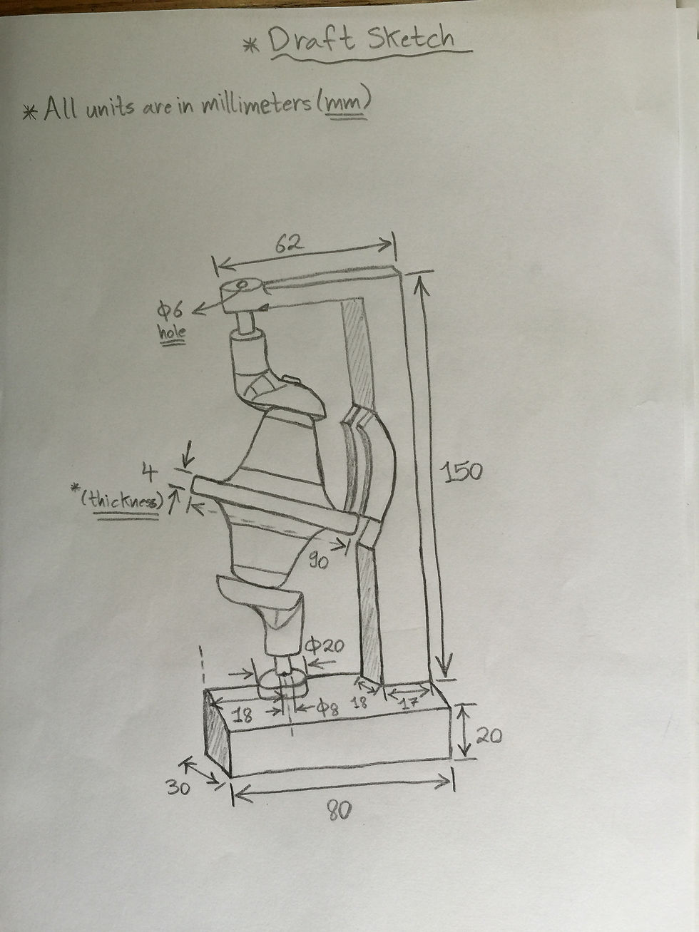
The very first step one should do when going through the process of making any CAD design is to show the "Design Concept" of his/ her design through a simple free hand sketch or draft to indicate and highlight the main features, components, and dimensions of such design. Therefore, in figure 1 you can see that I drew a simple sketch of the Arandela mechanism in order to just showcase the idea while further details will be shown through the 3D model design on Solidworks in the next step.

Working with SOLIDWORKS
The process of making the model design on Solidworks consisted of three main and consecutive steps which are: (a) Designing each individual part, (b) Assembly of different parts, and (c) Applying 3D Simulation on the assembled design.
a) Designing each individual part:
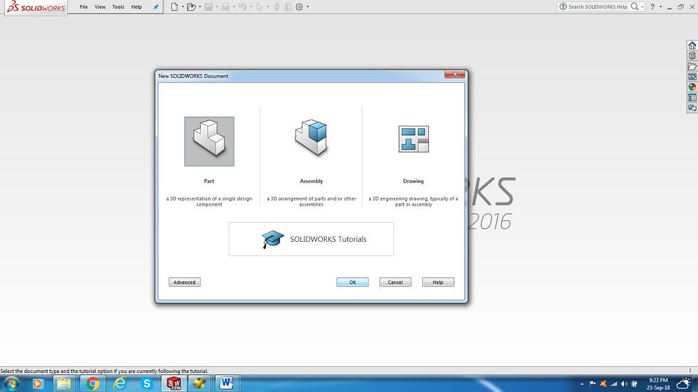
1. Open Solidworks, then choose "File" and select "New", choose "Part" as shown in figures 2 and 3 respectively.

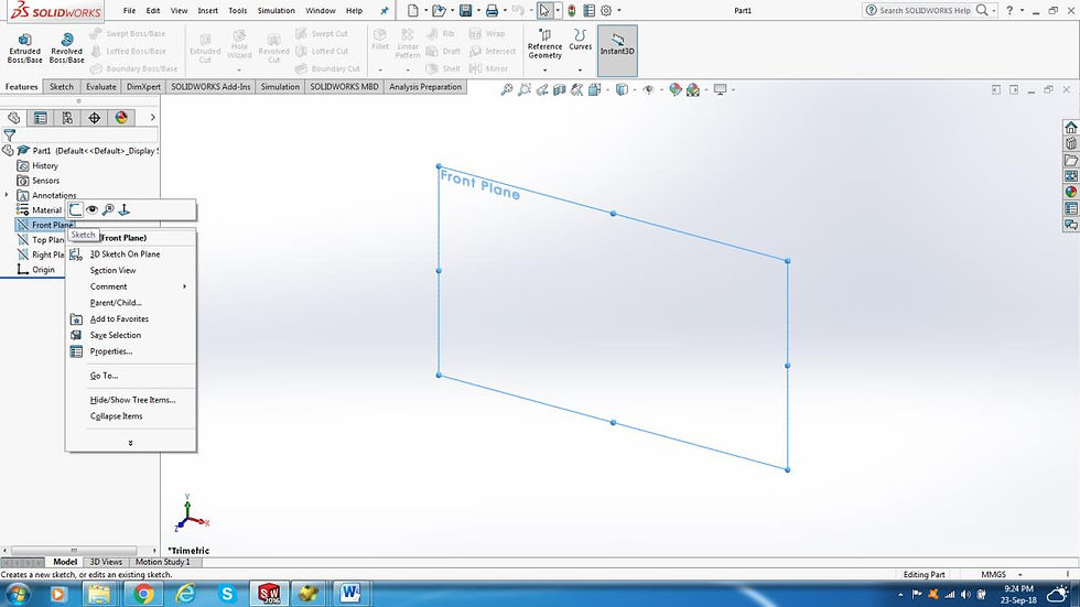
2. Select the plane that you will start your 2D sketch on whether (Front, Top, or Right Plane), then right click on it and choose "Sketch" as shown in figure 4.
Now, this Arandela mechanism consisted of four main parts:
1) Base
2) Arandela (Washer)
3) Crank
4) Pin
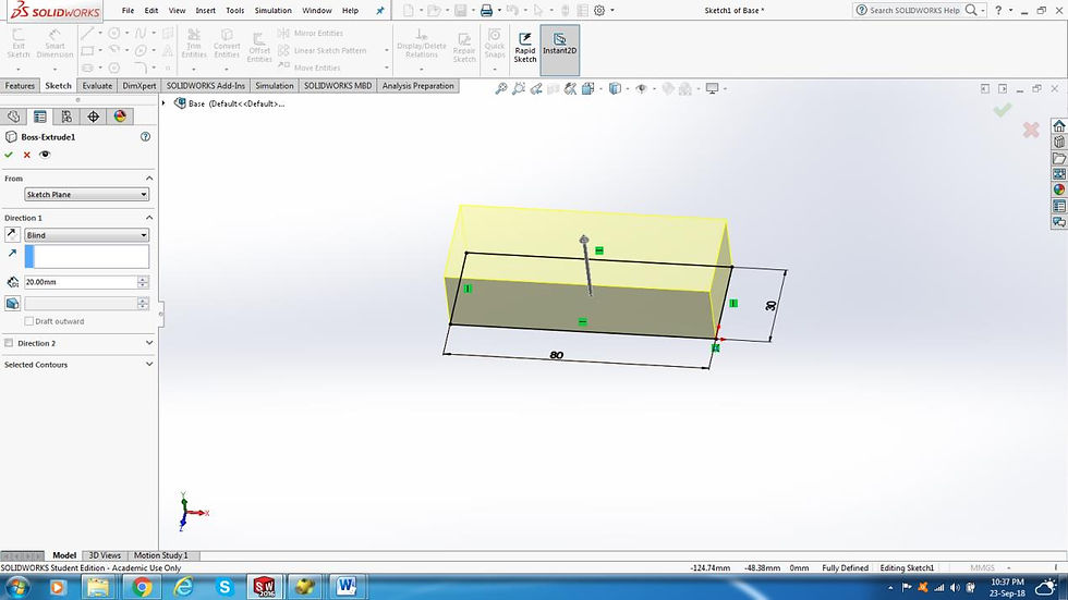
So, I worked on the design of each part as the purpose of this first step in the design process was to design every part individually then assemble them together afterwards. Hence, I started with the base of the mechanism by drawing a (80mm x 30mm) rectangle and extruding/ padding it with a 20mm thickness using the "Boss Extrude" command, which can be found in the "Features" tab at the top far left, as shown in figure 5. However, I then used further commands like for instance: "Extrusion Cut", "Linear Pattern", and "Fillets" in addition to assigning some design properties and constraints, like in figure 6, to complete the design of the whole base which had some complex geometries and dimensions as seen in figure 7.


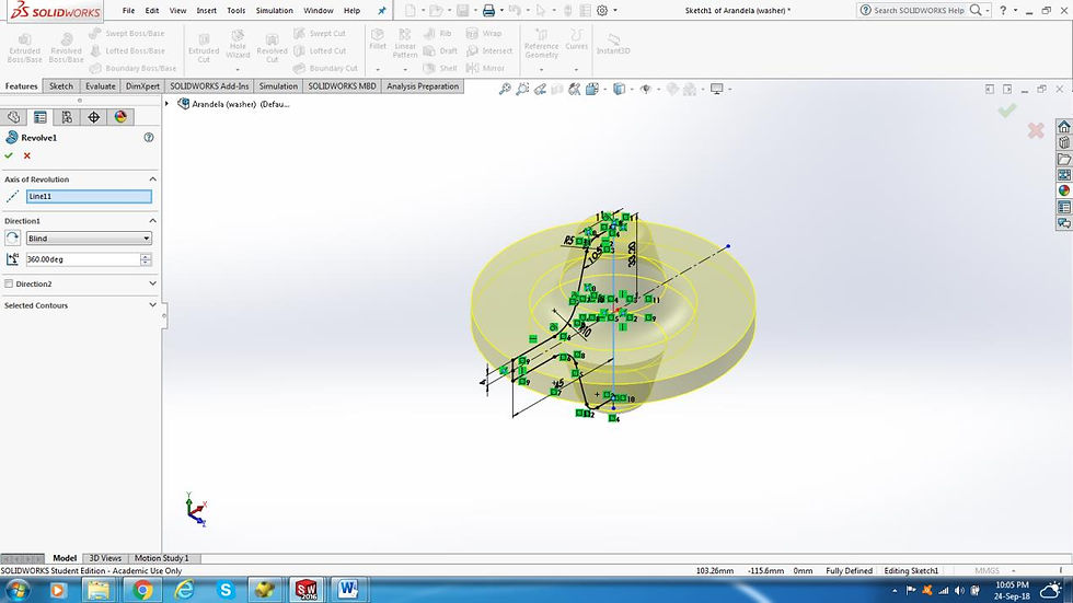
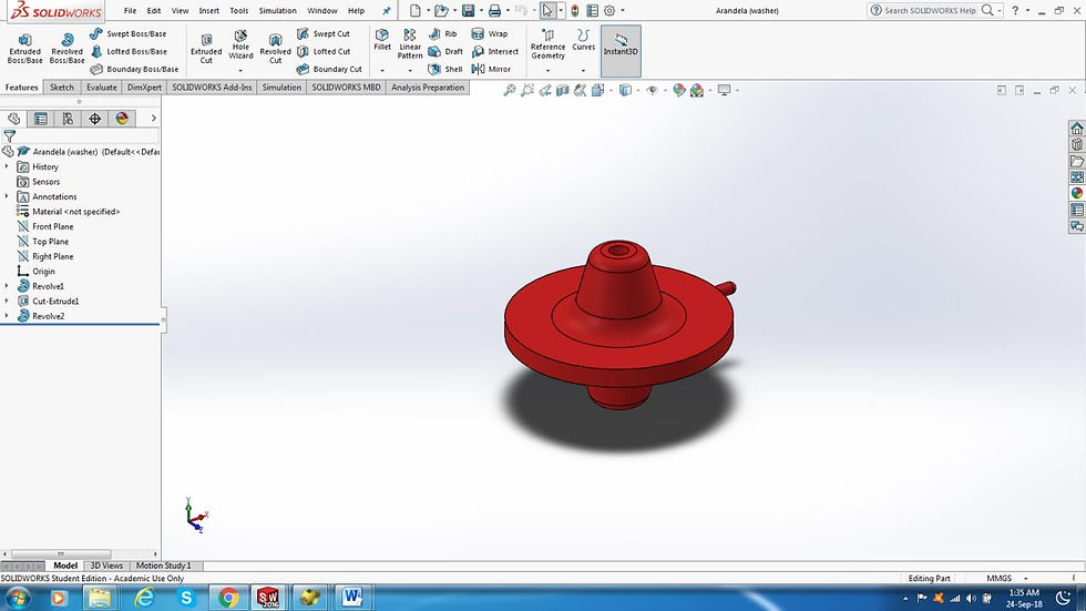
Then, and after the base was done, I worked on the design of the Arandela itself or the washer which had various aspects in its 2D sketch like different fillets and angles, as shown in figure 8, and actually it was a little bit challenging design wise but nevertheless fun to do. Moreover, I used a "Revolved Boss/ Base" to create the 3D shape out of the 2D sketch of the washer as shown in figure 9. And finally, I had the full desired washer design shown in figure 10.

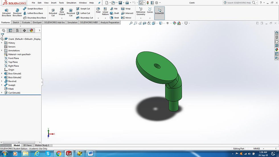
Afterwards, I worked on the design of the crank part and figures 11 through 15 show the different steps I went through, from 2D sketching to "extrusion" to "sweep" to "extrusion cutting" and so on, to create the fully designed crank shown in figure 15.


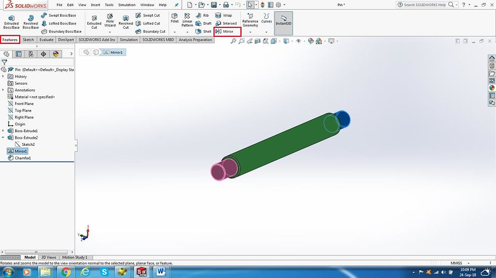
Finally, for the last part which was the pin I worked on the design and figures 16 through 19 show the steps in sequence, from 2D sketching to "extrusion" to "mirroring" of certain parts, to create the fully designed pin shown in figure 19.



b) Assembly of different parts:
The second step in our design process, once we finish designing all the individual parts, is to assemble all these parts together into one solid mechanism. In order to achieve this, we follow these simple steps:
1. Once again, we open Solidworks then choose "File" and select "New", however this time we choose "Assembly" as shown in figure 20.

2. Insert the different parts into the assembly environment using the "Insert Components" command, highlighted inside the red box in figure 21 below, to browse for the place where the components are saved.

3. Use the "Mate" command, which you will find directly beside the "Insert Components" command in the toolbar at the top, to join the different parts of the assembly together with various mating relations offered like: "Coincident", "Parallel", "Perpendicular", "Tangent" …etc., as shown in figure 22. After joining all the parts together using the necessary mates, you will a fully assembled mechanism like the one shown in figure 23.


c) Applying 3D simulation on the assembled design:
Finally, for the third and last part which was a bonus part, making a 3D simulation of the assembled mechanism requires going through the following steps:
1. Right click anywhere on the background and a large list of options and features will appear. Make sure that a feature called "Motion Manager", highlighted inside a red box in figure 24, is ticked.

2. Click on "Motion Study" which you can find at the bottom left corner. Once you go to motion study drag the black diamond shape in the window popping out from the bottom, indicated with a blue arrow on figure 25, to set the simulation time of this animation. Then, click on the "Motion Study Properties" icon, also highlighted inside a red box in figure 25, to set some features and properties in this motion study. (Note: In this step, make sure to choose the "Basic Motion" feature instead of the "Animation" feature so that the program compiler can later calculate the motion to deduce any errors in it!)

3. Once you have clicked on the "Motion Study Properties" icon indicated in step 2, a window will pop up on the left hand side, as shown in figure 26, and you will have to adjust some settings like:
Making the "Frames per second" equal to 30 or more so that the rendering of the simulation motion is not too slow.
Making the "Geometry Accuracy" and the "3D Contact Resolution" have a value of 8 which is an adequate value of both accuracy and resolution.

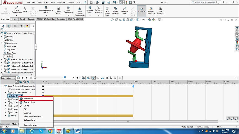
4. You will also need to place a "Rotary" motor at the base, because this washer mechanism like any other mechanism requires an actuator to start moving. So, click on the "Motor" icon, highlighted inside a red box in figure 27, and a window will pop up on the left hand side in the same place like step 3. Then, you need to adjust some settings like: making sure that the motor is "Rotary" not "Linear", setting the direction of rotation for the motor (C.C.W preferred), and adjusting the motor's RPM with an appropriate value for the mechanism like 30 rpm for instance as shown in figure 28. (Note: If you want to modify any of the motor's features later, you can right click on it from the list at the bottom left side and click "Edit Feature" as shown in figure 29!)


5. Now, it's time to press on the "Calculate" icon, shown in figure 30, so that Solidwork's compiler can simulate the motion and test for any errors or warnings.

6. Finally, press on the "Play" icon, shown in figure 31, and enjoy! :)

And here is a short video showing the 3D simulation (motion study) for the Arandela Mechanism on SOLIDWORKS version 2016:
A Brief Design Trial in OpenSCAD
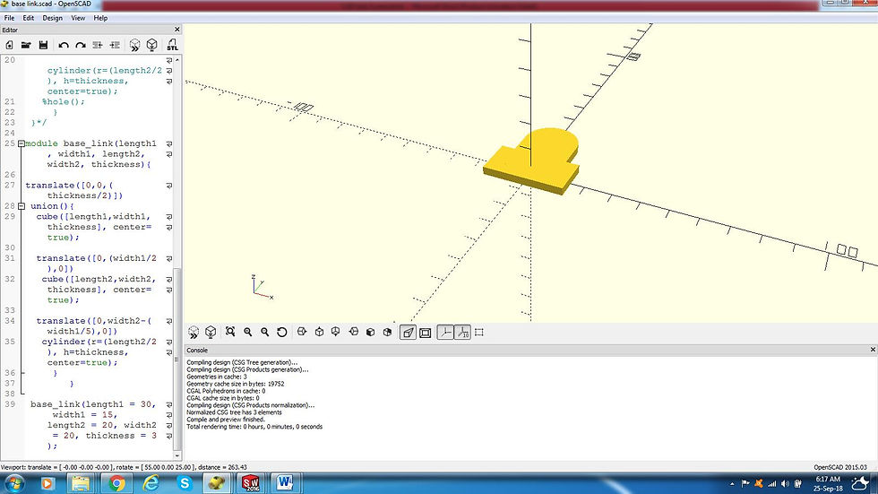
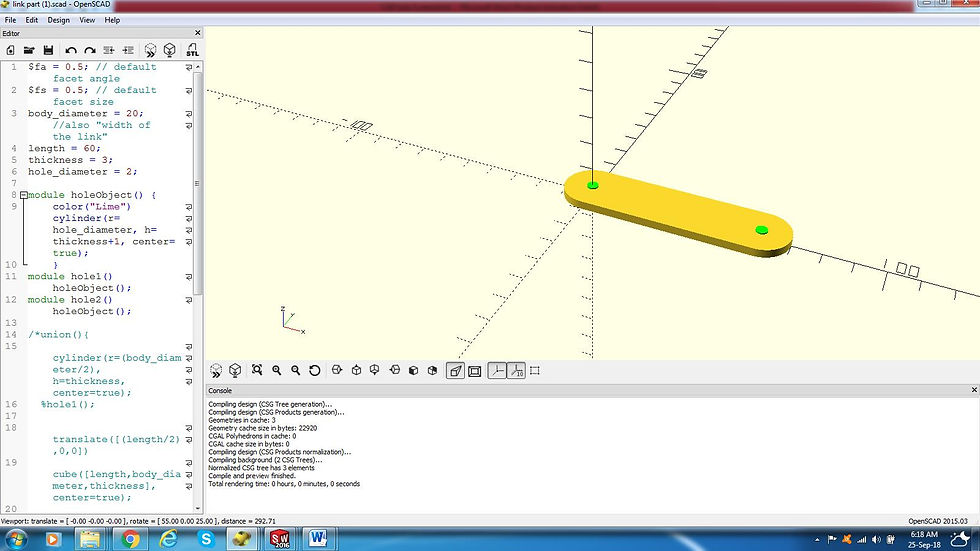
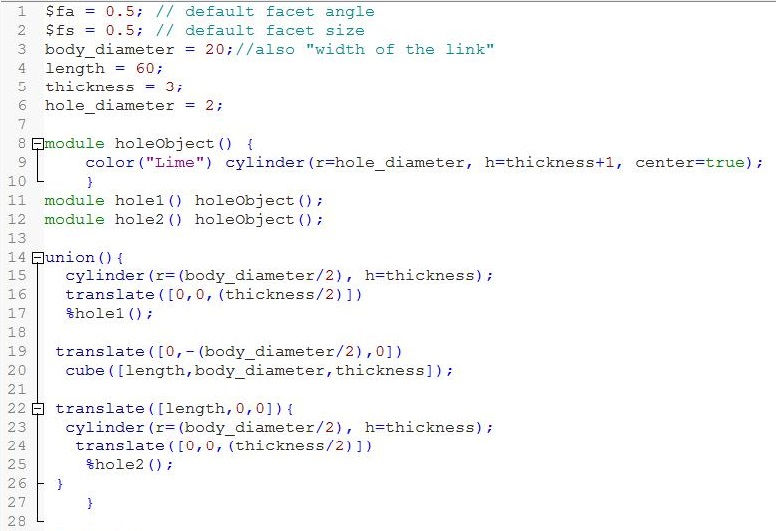
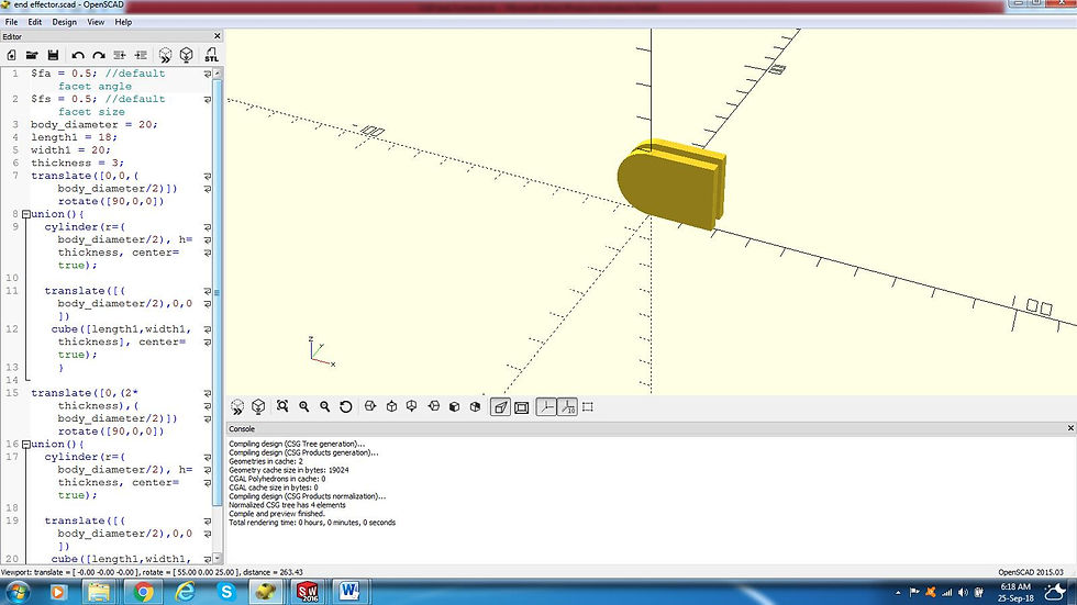
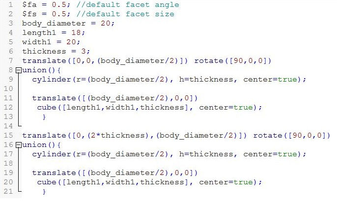
As another trial and for the sake of learning something new, as I'm already experienced in using Solidworks, I wanted to try out a somewhat unfamiliar CAD program and what better option than OpenSCAD! The best thing about this program is that it is open-sourced, free to use, requires very small memory space, and is really exciting to work with as you are doing all your parametric designs through lines of code and the syntax really isn't that hard too. So, I decided to give it a try and did some small designs with it which can be seen in the following figures along with their source codes. Unfortunately, I didn't have enough time to dig deep in it. However, I'm willing to continue working on it in the near future.



Conclusion
In summary, CAD drawing is a really interesting and powerful tool that helps us save time and effort compared to the conventional engineering drawing methods, increases our sense of imagination, and provides us with much help in terms of different libraries and analysis to work with. Finally, it's like using any tool and the more you practice it…the better you get! So enjoy designing and drawing :D
For more information and details about Computer Aided-Design, the steps of making my CAD model design on SOLIDWORKS, and my brief experience with OpenSCAD program. Please refer to the following link of a PDF file I made including everything you need to know about CAD.


Comments