

Task 8 - DC Motor Control using Electronics only (Group Task)
- EmadMaximos
- Oct 16, 2018
- 16 min read

Updated: Oct 22, 2018

Task Objective
The main objective of this group task was to control the motion of a DC motor making it move forwards, backwards, and stop with the aid of sensors and switches only without using neither push buttons nor any line of code. Therefore, the task was focused on controlling the motor's motion using pure electronics in order to better understand the concepts of electronics and the functions of the different components. We worked as a group of four members.
Introduction to the Components used
First, we need to go through a brief introduction to some of the components that we used to build our circuit which include the following:
Transistor
A transistor is a semiconductor device used to amplify or switch electronic signals and electrical power. It is composed of semiconductor material usually with at least three terminals for connection to an external circuit. A voltage or current applied to one pair of the transistor's terminals controls the current through another pair of terminals. Because the controlled (output) power can be higher than the controlling (input) power, a transistor can amplify a signal. Today, some transistors are packaged individually, but many more are found embedded in integrated circuits.
Most transistors are made from very pure silicon or germanium, but certain other semiconductor materials can also be used. A transistor may have only one kind of charge carrier, in a field effect transistor, or may have two kinds of charge carriers in bipolar junction transistor devices. Compared with the vacuum tube, transistors are generally smaller, and require less power to operate. Certain vacuum tubes have advantages over transistors at very high operating frequencies or high operating voltages. Many types of transistors are made to standardized specifications by multiple manufacturers.
Transistor as a Switch
Transistors are commonly used in digital circuits as electronic switches which can be either in an "on" or "off" state, both for high-power applications such as switched-mode power supplies and for low-power applications such as logic gates. Important parameters for this application include the current switched, the voltage handled, and the switching speed, characterized by the rise and fall times.
In a grounded-emitter transistor circuit, such as the light-switch circuit shown in the figure below, as the base voltage rises, the emitter and collector currents rise exponentially. The collector voltage drops because of reduced resistance from collector to emitter. If the voltage difference between the collector and emitter were zero (or near zero), the collector current would be limited only by the load resistance (light bulb) and the supply voltage. This is called saturation because current is flowing from collector to emitter freely. When saturated, the switch is said to be on.

Providing sufficient base drive current is a key problem in the use of bipolar transistors as switches. The transistor provides current gain, allowing a relatively large current in the collector to be switched by a much smaller current into the base terminal. The ratio of these currents varies depending on the type of transistor, and even for a particular type, varies depending on the collector current. In the example light-switch circuit shown, the resistor is chosen to provide enough base current to ensure the transistor will be saturated.
In a switching circuit, the idea is to simulate, as near as possible, the ideal switch having the properties of open circuit when off, short circuit when on, and an instantaneous transition between the two states. Parameters are chosen such that the "off" output is limited to leakage currents too small to affect connected circuitry; the resistance of the transistor in the "on" state is too small to affect circuitry; and the transition between the two states is fast enough not to have a detrimental effect.
Transistor as an Amplifier
The common-emitter amplifier, shown in the figure below, is designed so that a small change in voltage (Vin) changes the small current through the base of the transistor; the transistor's current amplification combined with the properties of the circuit means that small swings in Vin produce large changes in Vout.

Various configurations of single transistor amplifier are possible, with some providing current gain, some voltage gain, and some both. From mobile phones to televisions, vast numbers of products include amplifiers for sound reproduction, radio transmission, and signal processing. The first discrete-transistor audio amplifiers barely supplied a few hundred mill watts, but power and audio fidelity gradually increased as better transistors became available and amplifier architecture evolved. Modern transistor audio amplifiers of up to a few hundred watts are common and relatively inexpensive.
Light Dependent Resistor (LDR)/ Photoresistor
A photoresistor (or light-dependent resistor, LDR, or photocell), shown in the figure below, is a light-controlled variable resistor. The resistance of a photoresistor decreases with increasing incident light intensity; in other words, it exhibits photoconductivity. A photoresistor can be applied in light-sensitive detector circuits, and light- and dark-activated switching circuits.

A photoresistor is made of a high resistance semiconductor. In the dark, a photoresistor can have a resistance as high as several megohms (MΩ), while in the light, a photoresistor can have a resistance as low as a few hundred ohms. If incident light on a photoresistor exceeds a certain frequency, photons absorbed by the semiconductor give bound electrons enough energy to jump into the conduction band. The resulting free electrons (and their hole partners) conduct electricity, thereby lowering resistance. The resistance range and sensitivity of a photoresistor can substantially differ among dissimilar devices. Moreover, unique photoresistors may react substantially differently to photons within certain wavelength bands.
Variable Resistor/ Potentiometer
A potentiometer is a three terminal resistor in which the resistance is manually varied to control the flow of electric current.

It consists of three terminals among which two are fixed and one is variable. The two fixed terminals of the potentiometer are connected to both ends of the resistive element called track and third terminal is connected to the sliding wiper, as shown in the figure below. The wiper that moves along the resistive element varies the resistance of the potentiometer. The resistance of the potentiometer is changed when the wiper is moved over the resistive path. The resistive element of the potentiometer is either flat or angled. If the resistive element is flat, the wiper moves linearly. On the other hand, if the resistive element is angled, the wiper moves in a rotary manner.

The materials used to construct the resistive element of the potentiometer include: carbon particles in plastic, graphite, resistive wires, and cermets (combination of ceramics and metals). Potentiometers are also sometimes referred as pots.
Increasing or decreasing the resistance of the potentiometer controls the flow of electric current. If we increase the resistance of the potentiometer, large amount of electric current is blocked and only a small amount of electric current is allowed. On the other hand, if we reduce the resistance of the potentiometer, a large amount of electric current is allowed and only a small amount of electric current is blocked.
Applications
Potentiometers are used to control volume in audio equipments, frequency attenuation, changing loudness, and changing other characteristics of audio signals.
Potentiometers are used in televisions and computers to control the picture contrast and brightness.
Relay
A relay is an electrically operated switch. Many relays use an electromagnet to mechanically operate a switch, but other operating principles are also used, such as solid-state relays. Relays are used where it is necessary to control a circuit by a separate low-power signal, or where several circuits must be controlled by one signal. The first relays were used in long distance telegraph circuits as amplifiers: they repeated the signal coming in from one circuit and re-transmitted it on another circuit. Relays were used extensively in telephone exchanges and early computers to perform logical operations.
A type of relay that can handle the high power required to directly control an electric motor or other loads is called a contactor. Solid-state relays control power circuits with no moving parts, instead using a semiconductor device to perform switching. Relays with calibrated operating characteristics and sometimes multiple operating coils are used to protect electrical circuits from overload or faults; in modern electric power systems these functions are performed by digital instruments still called "protective relays".
Magnetic latching relays require one pulse of coil power to move their contacts in one direction, and another, redirected pulse to move them back. Repeated pulses from the same input have no effect. Magnetic latching relays are useful in applications where interrupted power should not be able to transition the contacts. They can also have either single or dual coils. On a single coil device, the relay will operate in one direction when power is applied with one polarity, and will reset when the polarity is reversed. On a dual coil device, when polarized voltage is applied to the reset coil the contacts will transition. AC controlled magnetic latch relays have single coils that employ steering diodes to differentiate between operate and reset commands.
Since relays are switches, the terminology applied to switches is also applied to relays; a relay switches one or more poles, each of whose contacts can be thrown by energizing the coil. Normally open (NO) contacts connect the circuit when the relay is activated; the circuit is disconnected when the relay is inactive. Normally closed (NC) contacts disconnect the circuit when the relay is activated; the circuit is connected when the relay is inactive. All of the contact forms involve combinations of NO and NC connections, as shown in the figure below.

DC Motor
A DC Motor is an electric motor designed to be run from a direct current (DC) power source. It has been more than 100 years that Brushed DC Motors are used in industry, and domestic applications.
A DC motor is an electrical machine and operates on the principle “Whenever a current carrying conductor is placed in magnetic field it experience a force”. The simplest form of a Brushed DC motor is a two pole motor design like the one shown in the figure below. This design is the best to understand the forces and rotation.

The force is given by the formula: F = B * I * L
Where F represents force, B magnetic field, I current and L is for length of the conductor. As the force is a vector quantity it must have a direction too. For finding direction of this force we apply Fleming’s left hand rule. If we know the magnitude as well as direction then we can get useful work from a DC Motor.
The main components of DC Motors are Windings, Magnets, Rotors, Brushes, Stator and the source of direct current as shown in the figure below. When the armature is placed in a magnetic field generated by the magnets or field windings and the armature is rotated by using direct current it results in the generation of mechanical force according to the above statement. We can utilize this force for doing any type of particular work that we want.

When the armature rotates in the magnetic field and it cuts the magnetic lines of force then an emf is induced in the system. This emf is termed as back emf as it opposes the armature current. Due to this back emf some energy is lost in the process. But a back emf is also required to make the dc motor work regularly without a back emf we can’t put load to the motor and hence getting the work done from motor becomes pretty difficult for us.
Hobby Plastic Gear Motors
For our application, we used this small plastic DC geared motor, shown in the figure below, which operates at 6V. At a lower cost than metal gearmotors, these motors with plastic gearboxes can be the ideal drive system for a small robot and for the use in prototype circuits. The gears are typically long lasting nylon and the motors fit a range of different wheels.

Steps of making our circuit
Now that we have introduced our components, lets discuss and show in details the exact steps that we went through to accomplish our group task. The task was divided into three main and consecutive steps which included: (a) Working on the circuit design, (b) Making the circuit design and PCB board on EAGLE, and (c) Implementing the circuit in hardware.
a) Working on the circuit design:
In this first step, we come up with the idea of our circuit design by simply free-hand sketching our circuit along with all the required components that we will be using and the necessary connections between them as shown in the figure below. The circuit connections will be discussed in more details later in this section.

Here is a table showing all the required components along with their assigned numbers on the figure above, their functions, and the quantity of each component that we used.

And here is also a detailed bulleted list of all the connections for each component in the circuit.
Connections:
Transistor 2N2222: this acts as the switch transistor; we have two of them and each has three legs (Ct - Bt - Et), the collector (Ct) to which the load is connected, which in this case are the relays as they are connected to the actual load (DC motor), so it connects to the relay's first coil end (coil end 1) to provide the input signal originally coming from the LDR sensor in addition to being connected to the amplifier transistor's collector (Ca) too, the base (Bt) is connected to both the LDR sensor and the potentiometer, and the emitter (Et) is connected to the amplifier transistor's base (Ba).
LDR Sensor: we have two of them and each has two terminals, one is connected to the Vcc (5V) while the other is connected to the switch transistor's base (Bt).
Transistor BC547: this acts as the amplifier transistor; we have two of them and each also has three legs (Ca - Ba - Ea), the collector (Ca) also connects to the relay's first coil end (coil end 1) to amplify the input signal originally coming from the LDR sensor in addition to being connected to the switch transistor's collector (Ct) too, the base (Ba) is connected to switch transistor's emitter (Et), and the emitter (Ea) is directly connected to the ground.
Potentiometer B10k: we have two of them and each also has three legs, one of the side legs is connected to the switch transistor's base (Bt) and the middle leg is directly connected to the ground.
Relays: we have two of them and each has five legs (NO - NC - C - coil end 1- coil end 2), the normally open (NO) switch legs in the two relays are both connected to each other with a common junction/ node connected to the Vcc (5V), the normally closed (NC) switch legs in the two relays are also both connected to each other but with a common junction/ node connected to the ground, the common (C) legs in both relays are connected to the two motor terminals, the first coil end (coil end 1) in both relays is connected to both the switch transistor's collector (Ct) and the amplifier transistor's collector (Ca) at the same time, and finally the second coil end (coil end 2) in both relays is directly connected to the Vcc (5V). (Note: There must be a potential difference between the two ends of a relay's coil so that current would flow in the coil magnetizing it in order for the relay to latch properly.)
DC Motor: as discussed in the relays' connections, the motor has its two terminals connected to the commons (C) of the relays.
9V Battery: its positive terminal is connected to the positive Vcc line of the breadboard and its negative terminal is connected to the negative ground line of the board to close the circuit and supply power to it.
b) Making the circuit design and PCB board on EAGLE:
This was our second encounter with "EAGLE", so we already had enough experience to know the program tools that can be used to make schematic circuit designs and printed circuit boards (PCBs). Plus, the program is really simple and interesting to work with in addition to having an immense library that includes various electronic components. The steps of working on EAGLE were as follows:
1. Open "EAGLE Autodesk 9.1.3".

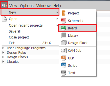
2. When the GUI of the program opens, you can choose either one of two things to do on EAGLE which are:
a) Schematic (To make a schematic design of your circuit).
b) Board (To make a Printed Circuit Board/ PCB out of your circuit).
By clicking "File", going to "New", and choosing either "Schematic" or "Board" as shown in the figures below.

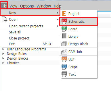

3. We choose "Schematic" as we first start by drawing the schematic design of the circuit and the following GUI for schematic appears, as shown in the figure below, that we will be using.

4. Now, we go to "Options" and select "User interface" to change the background color. We can choose from either white, black, or colored background as shown in the figures below. I personally choose the white background as I'm used to it.


5. We can also make a grid in our background, if we so choose, as shown in the figures.


6. Then, we start assigning the commands for shortcuts so that we can work fast and easily on schematics. We go to "Options" also, but this time we select "Assign" and a window pops up and then we choose "New" to assign a new command. Our command list includes:
1) Ctrl+A, Command Name: Add, for adding a component from the library.
2) Ctrl+D, Command Name: del, for deleting a component.
3) Ctrl+J, Command Name: jun, for making a junction for each component.
4) Ctrl+M, Command Name: mov, for moving/ rotating a component.
5) Ctrl+W, Command Name: wire, for adding connection wires between components.
All the steps required for assigning our commands/ shortcuts are shown in the following figures below.


7. Now, we try the Console commands like typing " add ", as shown in the figure below, or alternatively pressing Ctrl+A to add a new component from the library.

8. The GUI window for "Add" appears, we start searching for our components by writing down their names or codes in the "Search" bar located at the bottom. We add each of our required components individually as shown in the figures below. Important Notes:
This is the only way we can use to add a component in EAGLE. For example, if we are looking for a resistor and type in the word "resistor" in the console bar above the schematic the program won't understand! Therefore, we have to follow steps 7 and 8 to add a component.
When adding a component we should make sure that it has a PCB drawing, otherwise we won't be able to use it in making a PCB board for our circuit.
Sometimes a component can be found in the default Alphabetic library without needing to enter its name or code in the search bar.


9. By clicking "OK" after selecting the component that you want, this is how it looks like in the schematic, as shown in the figure below, and you can start clicking every where on the schematic to add more of the same component.

10. And this is after adding all the components.

11. Here we just adjust the orientation of some components by clicking on the component and pressing Ctrl+M to move it, in addition to right clicking on the component to make it rotate around.

12. Afterwards, we start adding junctions, which are the green dots shown below, by pressing Ctrl+J or writing "jun" in the console bar. We add them to all ends/ terminals of the components to ensure when using wires that the wire is correctly connected between the components.

13. Now, comes the time to use the wire command by pressing Ctrl+W or writing "wire" in the console bar. We add wires between components from one junction/ green dot to the other to have a final closed circuit as shown in the figures below.


14. By this point, the schematic circuit design is finished and now we go to making a PCB board out of this circuit by pressing the "Generate/ switch to board" icon in the toolbar at the top, then pressing "Yes" as shown in the figures below. This transfers us to the board GUI in EAGLE shown below.


15. So we start in the board GUI by assigning the commands for shortcuts so that we can work fast on the board. Again, we go to "Options", we select "Assign", and a window pops up and then we choose "New" to assign a new command. Our command list here includes:
1) Ctrl+M, Command Name: mov, for moving/ rotating a component.
2) Ctrl+P, Command Name: rip, for deleting wire connections on the board.
3) Ctrl+R, Command Name: rou, for routing new wire connections on the board.
All the steps required for assigning these commands/ shortcuts are shown in the following figures below.


16. We need to set some design rules before working on our board like: the clearance space between wires and the minimum distance between the board and the outlines of our square work space. In order to do so, we go to "Edit", then select "Design rules" and a GUI window pops up. We set the following parts:
In the "Clearance" tab, we set the wire clearance to be 5 millimeters (mm).
In the "Distance" tab, we set the "Copper/ Dimension" to be 60 mil.
All the steps required for setting our design rules are shown in the following figures below.


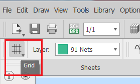
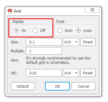
17. We also need to adjust our measuring units in the work space to be in millimeters (mm). Therefore, we go to the icon called "Grid" located at the top left corner of the window and press it. This opens up a small window GUI where we set the "Size" and "Alt" to be in mm as shown in the figures below.


18. Afterwards, we need to choose the PCB layer on which the wire connections will be made. We go to the tab named "Layer" also located at the top left corner of the window directly to the right of the "Grid" icon. Here, I choose the layer "16 Bottom" from the drop down list that appears, shown in the figure below, as we need to have our wires in the bottom layer, because the PCB that we will use will be having through holes and will not be a surface mount PCB.

19. Finally, we start routing our wire connections by pressing Ctrl+R. However, first we need to choose the wire style and width that we will use. I choose the wire style to be "Wire bend style 1" and a width/ thickness of 0.8128 mm, which is an appropriate width for our use, then we start the routing process as shown in the figures below.

20. And here we have our final PCB board circuit after routing all the wires.
Here is a screen recording video that we made showing the whole process of making the schematic circuit design of our DC motor control circuit on EAGLE:
c) Implementing the circuit in hardware:
The third and final step was to implement the circuit in hardware, however we had to connect the circuit on stages to make sure that every component is doing its job and working perfectly. We first connected the relay (without the load/ motor) with the switch transistor, the amplifying transistor, the LDR sensor, the potentiometer, and the power supply (battery) just to ensure that the relay is actually receiving a signal and latching accordingly as shown in the figure below.

Again, we did this for the other relay also connecting it with both transistors (the switch and amplifier), the LDR sensor, and another potentiometer for resistance adjustment.
And here is a video showing our test circuit working and the relay latching properly as we press on the LDR sensor:
Finally, it was time to test the circuit with the actual DC motor as shown in the figure below.

Here is a final video showing the whole circuit working and the DC motor rotating properly in both directions and stopping too:
Readings and Measurements:
As a bonus to our original work, we wanted to obtain some readings from the circuit, for later use to prove some of the transistor's equations, which we measured using a digital multimeter. However, for the readings we used Arduino as a power supply instead of the 9V battery and the readings were as follows:
Voltage on motor/load: 4V
Resistance of potentiometer (Threshold Resistance): 1.86kΩ
Voltage on base of amplifier and its LDR:
LDR ON: 0.8 V
LDR OFF: 0.44 V
Voltage on the collector of amplifier transistor with Vcc-Battery (Vc): 4.12V
Voltage on the collector of amplifier transistor with Ground (Vce): 0.7 V
Conclusion
To sum up, this task was really helpful in making us understand the basic fundamentals of electronics and how electronic circuits operate in general through practically working with various components and learning the theory of operation for each of them individually to perform our simple application. So, we encourage you to come visit us at FabLab in New Cairo (FLiNC) where you can learn and work with many types of electronics and start making your own unique application using electronics! :D


Comments